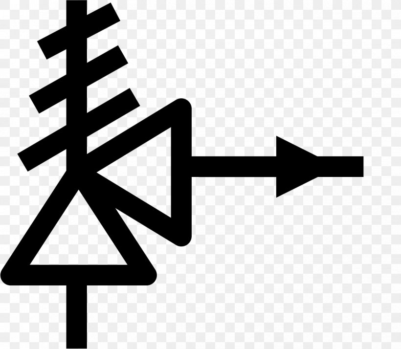
Temperature And Pressure Relief Valve Symbol

Commonly Used Safety Valves P Id Symbols Enggcyclopedia

P Ids Piping Instrumentation Diagrams And P Id Valve Symbol Library Assured Automation
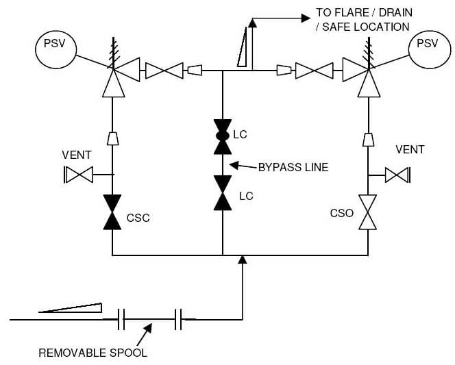
P Id Guidelines For Pressure Safety Valves Instrumentation Tools
Pressure Relief Valve Symbol Icon Royalty Free Vector Image
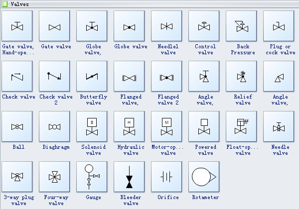
Process Flow Diagram Symbols
Relief Valve Safety Valve Gate Valve Piping And Instrumentation Diagram Png 1222x1065px Valve Area Ball Valve
The pressure and temperature relief valve ptr is designed to relieve the increase in pressure caused by water expansion during the normal heating cycle in a hot water tank.
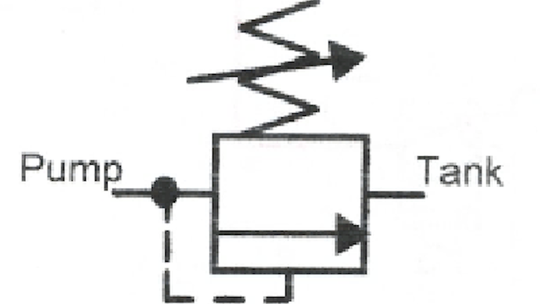
Temperature and pressure relief valve symbol. The relief valve in a well designed hydraulic circuit never relieves oil to tank unless there is a circuit or control malfunction. A direct acting relief valve responds quickly when pressure tries to go above the valve s setting. Uqm produces motors and inverters ranging in power transmission capability to 250 kw. Figure 18 1 pictures the symbol for a direct acting relief valve.
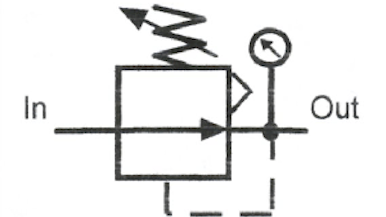
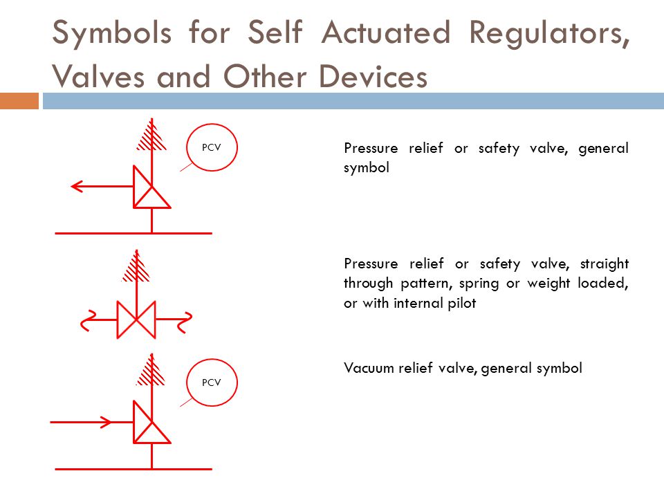
The relief valve is designed or set to open at a. P id symbols for following safety valves pressure relief valve vacuum relief valve breathing valve pressure rupture disc vacuum rupture disc etc. The pilot pressure also comes straight from the supply line upstream of the valve showing that as the pressure before the valve increases it pushes the arrow against the spring and relieves the pressure. Danfoss a s announced the acquisition of uqm technologies inc longmont colo a developer and manufacturer of power dense high efficiency electric motors generators power electronic controllers and fuel cell compressors for the commercial truck bus automotive marine and industrial markets.
The valve will then relieve the increase in pressure by releasing drips of hot water to the drain line. A relief valve or pressure relief valve prv is a type of safety valve used to control or limit the pressure in a system. Here in the image above the first symbol is of angle valve. Now the breather valve is used on the cone roof tank.
This valve serves the function of the relief valve and vacuum valve. Note how the arrow is shown in it s deactivated position e g. A pressure relief valve in which the bore area is equal. Pressure might otherwise build up and create a process upset instrument or equipment failure or fire.
All ports closed will increase the system pressure to the maximum actuating the pressure relief valve. Every square box indicates one valve position. The way to decipher a direction control valve symbol is as follows. The central position is a neutral position and various neutral positions are available depending upon the application.
The top symbol shows a simple direct operated pressure relief valve. The next symbol is of relief valve that used to protect the piping system or equipment from overpressure. In most cases a globe valve is used as an angle valve. The pressure is relieved by allowing the pressurized fluid to flow from an auxiliary passage out of the system.
T p valves used on residential water heaters are typically designed and manufactured to relieve pressure at 150 psi and temperature at 210 degrees f. A pressure relief valve in which the flow path area below the seat is less than the flow area at the inlet to the valve.

A Guide To Common Hydraulic Symbols Engineeringclicks
Industrial Process Control Standards Ppt Video Online Download

Hydraulics Unloading Valve Basic Principle And Symbol Hydraulic Valve

Design Elements Valves And Fittings Design Elements Valves Retract Resistor Check Valve Application Check Valve Symbol Direction Of Flow

Hydraulic Sequence Valve And Pressure Reducing Valve Hydraulic Valve
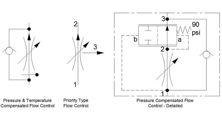
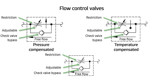
Flow Control Valves Hydraulic Symbology 204
Book 2 Chapter 18 Pressure Relief Valves Hydraulics Pneumatics
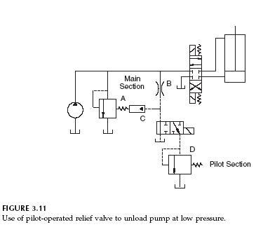
Pilot Operated Relief Valves Hydraulic Circuits Hydraulic Valve
Reading Fluids Circuit Diagrams Hydraulic Pneumatic Symbols

Fluid Power Basics Archives Andersons Hydraulics
Piping And Instrumentation Diagram P Id Enggcyclopedia

Overpressure Protection Devices Industrial Process Safety And Instrumentation Automation Textbook

Design Elements Valves Design Elements Valves Design Elements Fluid Power Valves Valve Symbols